Expert Support
Available 24/7 via chat
Available 24/7 via chat

Energy storage manufacturing lines bring together clean handling of cells with machining, welding, and assembly in one building.
Without proper zoning and air filtration, contaminants migrate from “dirty” areas into sensitive ESS cell, module, and pack assembly zones.
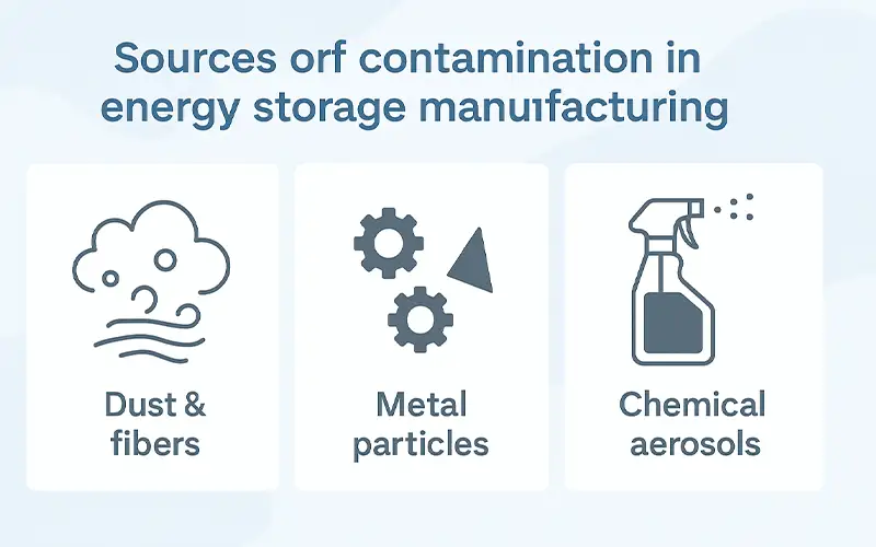
Three main groups of contaminants need to be controlled: general dust and fibers, conductive metal particles, and chemical aerosols from process materials.
In large ESS workshops, cardboard, wooden pallets, operator clothing, and building dust continuously shed fibers and coarse particles.
These can settle on cell terminals, insulation parts, or sealing surfaces, increasing contact resistance or becoming ignition fuel during a fault. Industrial ventilation is recognized as a primary control method for airborne dust; for example, OSHA’s guidance on
industrial ventilation highlights using supply and exhaust systems to keep dust at acceptable levels (industrial ventilation solutions). When you design air handling and filtration for ESS, these “background” dust sources must be treated as part of the contamination load, not ignored as harmless.
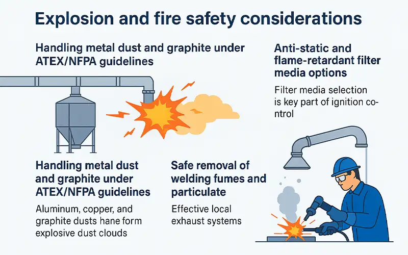
CNC busbar machining, enclosure stamping, and laser or resistance welding all generate metallic fines and fumes. These conductive particles can bridge gaps, damage insulation, or lodge in modules and packs, raising the risk of micro-shorts and localized heating.
NIOSH documents that welding fumes contain metals such as iron, manganese, chromium, and nickel and are associated with significant health and exposure concerns, which is why local exhaust ventilation and capture at source are strongly recommended (NIOSH welding fumes overview). For ESS manufacturing, the same principle applies: capture metal fumes and particulates at the tool, filter them, and prevent recirculation into clean assembly zones.
Adhesives, sealants, potting compounds, and electrolyte filling operations release vapors and fine aerosols. These can condense on cooler surfaces such as cell cases, busbars, and connectors, creating leakage paths, altering surface resistance, or degrading sensor performance.
Industry safety guidance stresses that local exhaust and properly designed ventilation are the standard methods for controlling airborne vapors from resins and solvents, ensuring they are captured and filtered rather than spreading through the workspace (safe handling of adhesives and sealants).
In ESS plants, combining source capture with appropriate filtration stages keeps chemical aerosols away from high-voltage components and improves both worker safety and product reliability.
Contamination in energy storage manufacturing is not a cosmetic defect—it directly influences electrochemical behavior, electrical stability, and long-term system safety.
Dust, fibers, metallic fines, and chemical residues can interact with cells and modules in ways that slowly degrade performance or trigger sudden failures. Understanding these mechanisms is essential for designing a filtration strategy that protects both yield and safety.
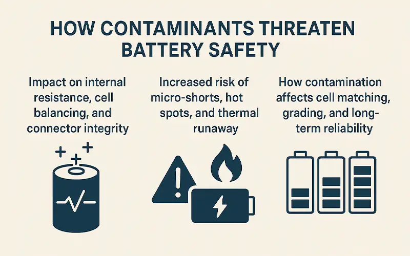
When particles settle on cell tabs, busbars, insulation films, or terminal contact points, they introduce micro‐gaps or uneven pressure across the interface.
This leads to unstable contact resistance and irregular current distribution during charging and discharging. Over time, these inconsistencies make automated cell balancing less effective, forcing the BMS to work harder to correct voltage drift.
Industry research on battery pack failures notes that poor interconnect quality and surface contaminants are key contributors to rising resistance and degraded efficiency, as documented in the U.S. Department of Energy’s analysis of battery failure modes (DOE battery performance data).
Conductive particles—especially metal fines from CNC machining or welding—pose a serious risk. Even microscopic fragments can penetrate porous separators or lodge between layers during cell stacking or module assembly.
These particles become conductive bridges, creating local micro-shorts that may remain latent for weeks before evolving into heat spots. If the localized temperature exceeds a threshold, it can trigger electrolyte decomposition or gas generation, escalating into thermal runaway.
Guidance on battery safety testing under UL 9540A emphasizes how internal faults and conductive debris can ignite cascading reactions in energy storage systems .
ESS module and pack assembly depend on precise cell matching—voltage, capacity, impedance, and leakage current all need tight tolerances. Dust or chemical residues on terminals, vents, or safety valves can alter measurement accuracy during grading and end-of-line testing.
Cells that appear acceptable during sorting may later show faster capacity fade, abnormal impedance growth, or increased self-discharge. Over the service life of an ESS system, these mismatched behaviors contribute to accelerated aging, BMS stress, and reduced usable capacity.
Contaminants also increase the likelihood of seal failures, moisture ingress, and corrosion—all of which shorten the lifespan of modules and racks.
By controlling airborne contaminants before they reach cell and module interfaces, manufacturers can maintain stable resistance, prevent internal faults, and ensure that matched cells remain balanced throughout their operational life. Clean air becomes a core safety mechanism rather than an environmental detail.
Air quality in energy storage system (ESS) factories is best controlled with a staged filtration strategy that follows the airflow from the air handling unit (AHU) to the final assembly areas.
Each stage targets a different particle size range and process risk, while keeping fan energy and filter life in balance.
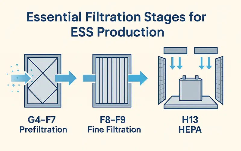
The first line of defense is G4–F7 prefiltration at the AHU or make-up air unit. These filters remove coarse dust, fibers, and debris from outdoor air and from recirculated air that has picked up contaminants in the workshop.
By capturing the bulk of larger particles early, prefilters protect coils and ductwork from fouling, and significantly extend the life of downstream fine and HEPA filters.
For ESS facilities that combine office, machining, and assembly spaces, robust prefiltration prevents general building dust from becoming a constant load on clean zones.
Downstream of prefilters, F8–F9 fine filters are used to remove the majority of sub-micron particles before air enters ESS assembly areas.
These stages are typically installed in central AHUs or dedicated air handling units serving cell sorting rooms, module assembly lines, and pack assembly zones. Fine filtration stabilizes particle levels so that terminal filters do not experience sudden loading spikes.
This is particularly important in large-format ESS factories where airflow volumes are high, and where open layouts can otherwise allow particles from logistics or packaging zones to drift into more sensitive processes.
For areas where cells are handled in open trays, where busbars and connectors are installed, and where insulation and sealing elements are exposed, H13 HEPA filtration is used as the final barrier.
These high-efficiency filters are often mounted in terminal housings or fan filter units (FFUs) above module and pack assembly lines. Their role is to ensure that the air directly bathing contact surfaces and insulation components is free from the fine dust and metallic particles that can cause contact resistance issues, micro-shorts, or long-term reliability problems.
Proper HEPA design includes uniform face velocity, tight gasket compression, and periodic leak testing to prevent bypass paths that undermine cleanroom performance.
In addition to general supply-air filtration, ESS production requires targeted capture of contaminants at their source.
Processes such as laser welding, resistance welding, busbar bonding, and limited CNC machining generate metallic fumes, particulates, and sometimes polymer smoke.
Local extraction hoods or on-tool extraction units draw these contaminants away from operators and components, passing the exhaust through appropriate prefilters and high-efficiency filters before discharge or recirculation.
This approach prevents conductive metal fines from entering the general air stream and reaching clean assembly zones, while also supporting occupational health requirements.
Combining staged supply-air filtration with well-designed local extraction creates a coherent air quality strategy that protects both worker safety and battery performance.
Effective moisture control is just as important as particle control in many energy storage manufacturing lines, especially where cell processing and electrolyte filling are involved.
Dry rooms and low-humidity zones must be designed as part of the overall air system, not as stand-alone “boxes.”
For ESS manufacturers working with different chemistries, understanding how moisture interacts with materials is key to choosing the right combination of dehumidification and air filtration.
Lithium iron phosphate (LFP) and nickel manganese cobalt (NMC) chemistries do not behave identically in the presence of moisture. NMC-based cells typically use electrolytes and active materials that are more sensitive to hydrolysis, leading to the formation of acidic by-products that attack current collectors and degrade the solid electrolyte interphase (SEI).
As a result, NMC production often demands stricter dryness targets in electrode processing and cell assembly. LFP, while generally considered more thermally stable and somewhat more tolerant, still suffers from moisture-induced degradation in binders, conductive additives, and electrolyte systems.
In both cases, uncontrolled humidity can translate into gas evolution, increased impedance, and reduced cycle life, but NMC lines tend to have tighter dew point and RH specifications throughout more of the process.
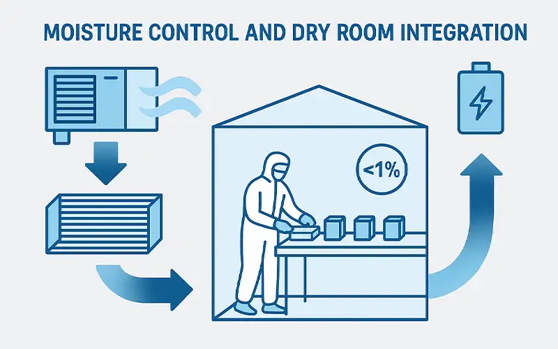
A dry room is not simply a space with dehumidifiers; it is an engineered environment where dehumidification and multi-stage filtration work together.
Typically, outside or mixed air first passes through G4–F7 prefilters to remove coarse dust, then through F8–F9 fine filters to reduce sub-micron particles before entering the desiccant dehumidifier or low-dew-point chiller system.
After moisture is removed, the air is often passed through terminal H13 HEPA filters at the ceiling or tool plenums to achieve both particle and moisture control at the point of use.
This sequence protects the desiccant wheel or cooling coils from fouling, stabilizes downstream particle counts, and ensures that ultra-dry air delivered to coating, calendaring, and stacking equipment is also clean.
Integrating airflow balance, pressure cascades, and recirculation ratios into this design prevents humid air from adjacent zones from leaking back into the dry room.
In cell processing environments, target humidity levels can be below 1% RH or at dew points of −40 °C or lower, depending on the chemistry and process specification.
Achieving these conditions is only half the challenge; the other half is keeping them stable during shift changes, material transfers, and equipment maintenance.
This requires tight building envelopes, airlocks with interlocked doors, low-leak penetrations, and procedures for pre-baking materials to remove absorbed moisture before they enter the dry room.
Continuous monitoring of dew point and RH at both supply and return, combined with differential-pressure monitoring across filters and room boundaries, helps operators react before excursions impact product quality.
When dry-room integration is done well, ESS manufacturers can maintain consistent cell quality across large volumes, reduce scrap and rework related to moisture defects, and support the long-term reliability demanded by grid-scale and commercial energy storage projects.
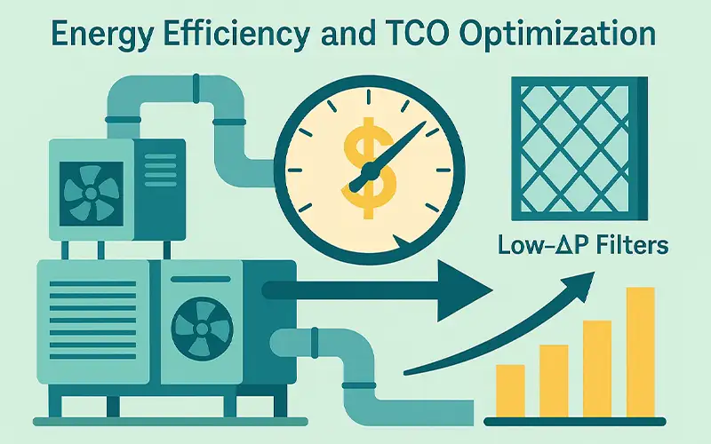
Energy storage system (ESS) factories operate high-airflow HVAC and cleanroom systems for long hours, often 24/7. That makes air filtration a major driver of operating cost, not just a technical necessity.
By choosing low-ΔP filters and protecting high-value stages with a well-designed filtration chain, plants can significantly reduce fan energy, extend filter life, and improve total cost of ownership (TCO) while keeping particle levels within tight limits.
Fan power is closely linked to the total pressure drop in the air system. In large ESS workshops with long duct runs, high air-change rates, and multiple filter stages, each Pascal of resistance translates into measurable energy consumption.
Low-ΔP filters use optimized media and pleat geometry to achieve the same or higher efficiency at lower initial resistance and a slower rise in pressure over time.
This allows supply and return fans to operate at lower speeds or static pressures while still delivering the required airflow to cell, module, and pack assembly areas.
Across multiple air handling units, even a modest reduction in average pressure drop can produce substantial kWh savings per year, especially in facilities running continuously.
HEPA and ULPA filters used over sensitive assembly lines are relatively expensive and disruptive to change, often requiring production downtime and retesting.
A strong upstream protection strategy—G4–F7 prefilters and F8–F9 fine filters with suitable dust-holding capacity—keeps the majority of coarse and sub-micron particles away from the terminal HEPA stage.
This slows the accumulation of dust in the high-efficiency media, stabilizes pressure drop, and extends the service interval for HEPA replacement.
Instead of changing terminal filters on a conservative time schedule, ESS manufacturers can use differential-pressure trends to manage condition-based maintenance, targeting change-outs when they deliver real value rather than as a precaution driven by upstream contamination.
Stable air quality has both direct and indirect financial benefits. Directly, lower fan energy, extended HEPA life, and reduced unscheduled maintenance cut operating expenses.
Indirectly, consistent particle and moisture levels reduce contamination-related defects in cell handling, busbar connections, and pack sealing. That leads to higher first-pass yield, fewer rework loops, and less scrap of high-value cells and modules.
When energy efficiency and TCO optimization are built into the filtration design—from low-ΔP media selection to smart staging and monitoring—air filtration becomes a strategic lever for ESS factories, supporting both competitiveness and long-term reliability of deployed energy storage systems.


Leave a comment